itutorial - It has the ability to operate DC motors at lower speeds Pulse Width Modulation (PWM) on the Arduino board microcontroller, namely setting the comparison or ratio tall And low (cycle) I really love you.
How to use PWM to operate a DC motor?
Setup Timer/Counter 1 10 bit fast PWM.
And this tent has many types of tents that can be installed using PWM so they can be used for a long time. cycle So the rotational speed of the dc motor can change so that grid line follower This may be the reason why it has nothing to do with it, but it also has the same control over it. The materials and images below are taken from the materials data sheet ATmega328P microcontroller IC.
 |
| Figure 1. Fast PWM timing diagram mode |
- TCNTn: register Timer/Counter which is used to count from 0 to maximum (depending on the bit ward off used) then from the maximum count down to 0 continuously and repeatedly. I don't need to eat anything timer activated.
- OCRnx: Is a register and is used to change cycleThe value in this register is compared with the TCNTn value, the result of which will change cycle Output pad or output on the OCnx pin or terminal.
- OCnx: List Compare Output They also have different options for registering TCNTn and OCRnx. OCnx is directly related to the pin or PWM terminal (PWM output).
PWM pins or terminals output used in the network grid line follower This uses pins 9 and 10 on the Arduino Uno because these pins work in 8, 9 and 10 bit PWM mode. By using this pin you can have many options if you want to change the PWM mode used. Timer/Counter 1 The register has several modes for using PWM as follows:
- PWM True Phase 8, 9 or 10bit
- Fast PWM 8,9, or 10bit
- Correct PWM Phase and Frequency
- PWM True Phase
- Fast PWM
PWM and other devices grid line follower this is using Fast PWM 10 bit. Maybe if you can use different modes according to the suitability of the dc motor you are using.

 |
| Figure 2. Register TCCR1A |
 |
| Figure 3. Register TCCR1B |

 |
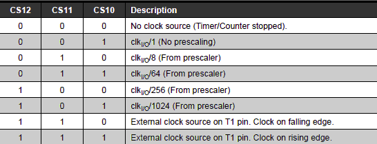
To configure fast 10 bit PWM And also has a TCCR1A register and TCCR1B adjustment register. For this you need to change the bits in each register according to the data options in tables 1, 2, 3 including Figure 2 and Figure 3 above.
- bit 0: WGM10 is 1
- bit 1: WGM11 is 1
- bit 2: Value 0
- bit 3: Value 0
- bit 4: COM1B0 is 0
- bit 5: COM1B1 is 1
- bit 6: COM1A0 is 0
- bit 7: COM1A1 is 1
So the TCCR1A value can be written as:
- bit 0: CS10 is worth 0
- bit 1: CS11 is 0
- bit 2: CS12 is 1
- bit 3: WGM12 is 1
- bit 4: WGM13 is 0
- bit 5: Value 0
- bit 6: ICES1 is 0
- bit 7: ICNC1 is 1
So the TCCR1B value can be written as follows:
- The bit value of WGM10, WGM11 is 1 and WGM12 is 1 and WGM13 is 0. Fast PWM mode 10 bit.
- The bit value COM1B1, COM1A1 is 1 and COM1B0, COM1A0 is 0, meaning it is using mode not flipping. This is what you are trying to do reverserAnd there are motorbikes that get the opposite speed, where if you want them to be fast they end up slow, and vice versa.
- In the TCCR1B register, the CS10, CS11, CS12 bits are 0, 0 and 1, which means that the PWM frequency is the speed frequency. clock crystal oscillator divided by 256 (clkio/256).
Because the setup uses 10bit fast PWM No need to use PWM is:

- Grid Line Follower Working Concept
- How Arduino Uno's PWM works for regulating dc motor speed
- Interrupt timer For line sensor reading
- Line Sensor Reading Program Code
- Mechanics and movement Grid Line Follower
- Complete Code Grid Line Follower
- PCB and Grid Line Follower Circuit
'Eelektronika' 카테고리의 다른 글
| Op-amps (0) | 2024.04.26 |
|---|---|
| Rectifier diode (0) | 2024.04.26 |
| JFET (Junction Field Effect Transistor) (0) | 2024.04.26 |
| N-MOSFET Amplifier Common Source (0) | 2024.04.26 |
| Scissors & Tongs (0) | 2024.04.26 |