반응형
Cutter It is a diode circuit whose function is to carry out clip (cut signal) against the signal enter without distorting the residual signal. Generally a series Cutter You'll definitely feel like you're at home noise Or a new waveform in a signal.
To facilitate understanding of understanding Cutter.
Basic circuit Cutter What do you want:
- Cutter series
- Cutter parallel
1. Network Cutter Series
Suite Cutter This will be the first day to return to the next day.
 |
| Figure 1. Basic circuit Cutter Series |
On the network Cutter Series 1 output. Output Signal errors occur simultaneously with 2 and Figure 3 without a triangle signal.
 |
| Figure 2. Truncated square signal (cut) low part |
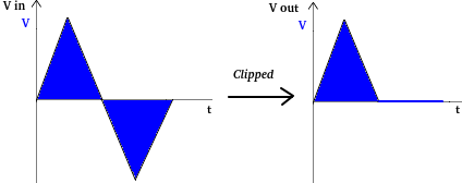 |
| Figure 3. Truncated triangle signal (cut) low part |
It's very easy to eat it Cutter Series
This will be the first step Cutter It is a series of half-wave rectifier diodes that are supplied with a DC voltage source arranged in series with the diode. Series bias circuit Cutter Has several network variations as follows: The series bias is reversed
 |
| Figure 4. Series bias Cutter |
Figure 4 shows that the current voltage VI together with VM And that's what happened V so output diode is 0. Several conditions that can occur in Figure 4 are as follows:
- Voltage enter (VI) must be greater than the dc voltage (V), so that the voltage output is voltage enter minus dc voltage (VI -V).
- If voltage enter (VI) is the same magnitude as the dc voltage (V) then the voltage output to 0 Volts (no output).
- If voltage enter smaller than the dc voltage then there is no current flowing through the diode or voltage output On the diode is 0 or no voltage.
Second variation
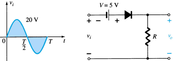 |
| Figure 5a. Signal enter Suite Cutter series with proceed biased |
Voltage enter This is the sine sinusoid in the circuit Figure 5a produces output Separately shown Figure 5b.
 |
| Figure 5b. Signal output scissor series with proceed biased |
Figure 5b shows that signal enter The circuit in Figure 5a has the form output There are also 5 days left in the room proceed biased by 5 volts then the signal enter increase the voltage level to 5 Volts so that the voltage is greater output (VHi) is the voltage inputT(VI) plus 5 Volts (VI +5 Volts).
2. Network Cutter Parallel
Suite Cutter The same number of people have six more days with the same number of people.
 |
| Figure 6. Basic circuit Cutter parallel |
Output signal circuit Cutter Parallel image 6 is cut off by half the positive signal wave as shown in Figures 7a and 7b.
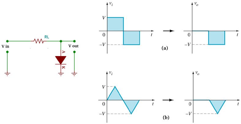 |
| Figure 7. Output Suite Cutter parallel |
Figure 7 shows that when a positive wave signal enters the circuit Cutter parallel, then the signal will be immediately discarded or channeled completely to land It's all about 0 Volts. When the negative half wave diode is in a state where no electric current flows which causes the negative half wave not to be cut and still intact.
It's very easy to eat it Cutter parallel
Biased on Cutter parallel is a series Cutter Parallel where the diode is given a good bias proceed nor come back. Figure 8 shows the circuit Parallel use proceed biased.
 |
| Figure 8. Bias voltage at parallel scissors |
Suite Cutter parallel to proceed bias has enter sinusoidal signal with voltage peak +16 Volts and -16 Volts and greater power at 8a. When going through the circuit Cutter parallel proceed biased by 4 volts then the signal enter There is also a 4 Volt power supply that can be connected to a cell phone output This may be the first time you have to read it again 8b. On signal enter The 4 volts above are used to operate at home.
Clamp
Suite Clamp You can't find anything like this clamp (slide) A signal to different DC levels. Clamp also often referred to as dc recovers. Suite Clamp itself consists of several components, namely:
- Capacitor
- Diode
- Element resistance (resistor)
The Clamper circuit is similar to the parallel Clipper circuit except that capacitors are added in series in the direction enter separate broand Figure 9.
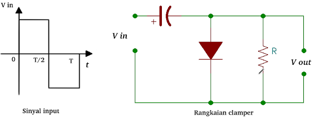 |
| Figure 9. Circuit Clamp |
If signal enter Here's what you need to know Clamp shown in Figure 9 is the signal form output Separately designated Figure 10.
 |
| Figure 10. Output Suite Clamp |
On signal enter The user's position is set to work with positive results today, but there is a list of people who have the same choice as his father, and he has many people who want to read it. Moment enter The negative half wave diode does not conduct electric currentBecause previously the capacitor stored an electric charge equal to the positive half-wave, the negative half-wave voltage is multiplied by the voltage stored in the capacitor so that the voltage in the negative half-wave becomes two ends (negative half-wave minus positive half-wave) which can be seen in the signal. output Figure 10.
1. Clamp with proceed biased
Clamp English tension proceed biased is a series Clamp Where the diode is given a dc voltage proceed This will be posted next month 11b.
Example of voltage calculation output Suite Clamp Figure 11b with signal enter Figure 11a. They are connected to each other Clamp Below it is assumed to use ideal components.
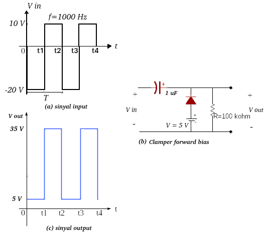 |
| Figure 11. Signal form enter And output Suite Clamp proceed biased |
On signal enter Figure 11a Enter the circuit Clamp Figure 11b, as well as several steps to calculate and determine the image output shown in Figure 11c, namely:
- During period 0 – t1 the voltage signal enter -20 Volts. Current flows in the diode and capacitor because the capacitor is considered short-circuited until it holds a full electric charge. It has a 20V power supply and a 5V power supply. Voltage output always measured 5 Volts, this is caused by the terminal output Placed on the cathode terminal and negative terminal battery.

Figure 12. Signal output period t0 – t1 - During the period t1 – t2 the voltage signal enter +10 Volt wave. The diode is in condition dead Or not connecting and discharging the capacitor (debit) The charge, so the voltage at the terminal output This is the sum of the voltage of +10 Volts and the voltage stored in the capacitor, which is +25 Volts, so the total voltage output measured is +35 Volts.

Figure 13. Signal output period t1 – t2
- During the period t2 – t3 the voltage signal enter This unit has a 20 Volt battery that can be installed (forward bias)then voltage enter 20 Volts can be used at all times proceed 5V diode bias because the -20 Volt voltage is converted to +20 Volts by the diode. Because the capacitor is empty, current flows through the diode and capacitor. Voltage at terminals output measured by voltage proceed 5 volt bias diode.

Figure 13. Signal output period t2 – t3 - During the voltage period t3 – t4 enter +10 Volts. There is a period during which users can use it can go home Or emit a charge which is added to the voltage enter It is 10 Volt and has a total capacity of 35 Volt.

Figure 15. Signal output period t3 – t4
There are 1 to 4 hinges to each other output Suite Clamp shown in Figure 16.
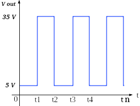 |
| Figure 16. Signal output period t3 – mn |
2. Clamp with come back biased
Clamp with come back bias is a series Clamp where a dc voltage source is added to the diode component which rotates from the direction of the current diode on We will send you the following list of items on the following page: 17b.
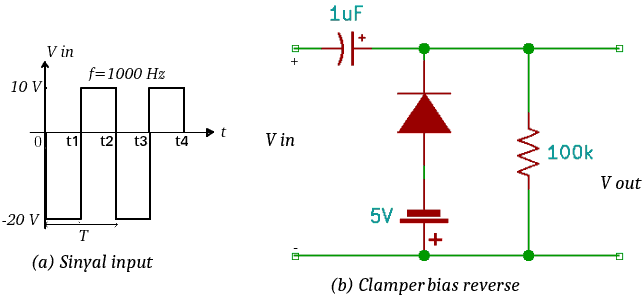 |
| Figure 17. Clamp with come back biased |
Figure 18 shows the signal shape output from the network Clamp Image Pad 17 days.
 |
| Figure 18. Signal form output Suite Clamp in Figure 17 |
Signal explanation output Draw the shape of the 18 day signal enter and network Clamp Figure 17 is as follows:
- During the next period 0 – t1 enter -20 Volts. This period is diode on And electric current flows through diodes and capacitors. Charging capacitor (cost) The list has a 20 Volt capacity, 5 Volt capacity, and 15 Volt capacity. There is another option available – 20 Volt, which can be installed on the other side. Because output The terminal is connected to the terminal and the positive terminal batterythen the voltage is measured at the terminal output is voltage come back battery namely -5 Volts.
- During the voltage period t1 – t2 enter +10 Volts. This period lasts for a certain period of time dead Or not deliver because the voltage at the cathode terminal is higher than the anode terminal. The capacitor produces an electric charge (debit) So that the voltage on the capacitor is also the voltage output It becomes bigger, namely 10 Volts added to the electrical voltage stored in the 15 Volt capacitor with a total of 25 Volts.
- During the voltage period t2 – t3 enter -20 Volts. During this period the capacitor is charged again (cost) Can be used at a voltage of 15 Volts every day between 0 and 10 days. Voltage output measured is – 5 Volts.
- During the voltage period t3 – t4 enter +10 Volts. This period is the same repetition as the period t1 – t2.
EOF