Itutorial - The FET keeps it ready Field Effect Transistors It is an electronic device with three terminals, namely Source (S), Gate (G) And Drain (D) where is the current outputt FET is controlled by voltage enter on the terminal Gate, FET Made from P and N type semiconductor materials, similar to BJT, the difference is the current output BJT will be happy again enter on the terminal Base currently output The FET current is controlled by the voltage at the terminals Gate. FET is generally also called JFET.
- JFET (Junction Field Effect Transistor)
- MOSFET (Metal Oxide Semiconductor Field Effect Transistor)
Junction Field Effect Transistors (JFET)
- Gate (G) PN junction. Then the doped area is called Gate (G).
- Source (S): Is the Input terminal where the majority carrier is (majority operator) Enters and passes through the semiconductor.
- Drying (D): Is the terminal where the electricity carrier exits from the semiconductor.
- Channel : Is an area of a semiconductor where most of the carriers pass through Source to Drying.
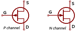 |
| Figure 1. JFET symbol |
JFET P channel
JFET P channel It is a JFET and has a thin N layer formed on a double-sided P type substrate. The N type thin layer on both sides is referred to as Gate.
 |
| Figure 2. JFET P channel |
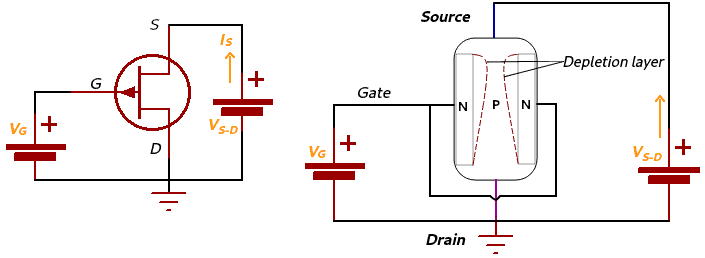 |
| Figure 3. Bias in JFET P channel |
Todead-can turn JFET on or off P channel What do you want to do:
- By breaking the biasive voltage at the terminal Sourceno need to worry about this list and what the terms are Source.
- No need to change the positive bias of the terminal Gate until thinning layer cover an area P channel. If the bias is positive at the terminal Gate Increased only slightly in the area thinning layer This is what I like P channel so area P channel Will narrow causing the current to pass through Source going to Drying getting smaller. There are many biases and positives in the future thinning layer second side Gate cover an area P channel The Maya Current cannot be bypassed Source to Drying And this one has the same JFET key dead.
JFET Characteristics P channel shown in figure 4.
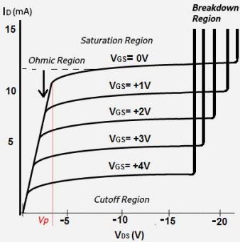 |
| Figure 4. JFET P Curve Characteristics channel |
Every day is full of 4 dinners VG.S You can use 0 Volts in it Velementary school This is what we are talking about Drain Source also up, when VDS reach voltage pinch off (VP) What arouses the passion that flows in Drain Source reaches a maximum point or saturation (IDSS) Where if voltage VDS This is the last time you log in pinch off There is a lot to discover in Konstan. If voltage VDS There is also a JFET option available details.
JFET N channel
 |
| Figure 5. JFET N channel |
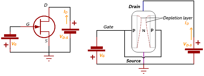 |
| Figure 6. Bias in JFET N channel |
- Breaks the bias voltage at the terminal Drying This will also help you reach your terminal Drying.
- Provides negative bias at the terminal Gate to both sides Gate thinning layer There are more and more menus available Drying to Source. If the bias is negative at the terminal Gate It's not big enough that's why thinning layer Doesn't cover the full path N channel so area channel It just becomes narrower so that current passes through it Drying to Source become small.
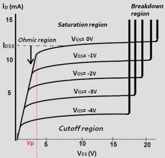 |
| Figure 7. Characteristic Curve JFET N channel |
Every day of Ramadan 7 days later, the next dayG.S You can use 0 Volts and replace VDS This is what we are talking about Drain Source also rises, when VDS reach voltage pinch off (VP) what is the current flowing at Drain Source reaches a maximum point or saturation (IDSS) where if the voltage is VDS This is the last time you will need to do this pinch off I don't know where Constant is. If voltage VDS There is also a JFET option available details.
The meaning of voltage pinch off (VP) And then the next one at the same timeDS minimum time the current is on Drying (ID) Constant Start even though the voltage is VDS Increased by condition VG.S = 0 Volts. If the JFET is in the same position then saturation will occur.
Various explanations region 4 day prayer at the end of 7 days:
- Ohmic region : The area where the JFET begins to show resistance to the current flowing from it Drying to Source (ID). No need to worry about what kind of response you get.
- Cut region : The area where the JFET is in condition or starting dead (no current ID flow).
- Saturation region : The area where the JFET works is full of current ID maximum. This area occurs during stress VDS Just that pinch off And VG.S = 0 Volts.
- Damage area : The area where the JFET gets bias voltage at the terminal Drain Source (VDS) Maximum or exceeding the voltage required by the transistor, then the JFET loses the ability to withstand current due to the voltage applied to it Drain Source too big. It can be used in JFET.
When the JFET is working on ohmic region The magnitude of the FET resistance can be determined using the equation:
RDS =VP /IDSS
RDS Ohmic resistance
If data sheet JFET shows VP =4V And IDSS=10mA I do not believe ohmic region is:
RDS = 4 Volts / 10mA = 400 Ohms
When the JFET tip comes out of the box each JFET is usually on where is the terminal Gate worth 0 volts Or there is no voltage enter JFET can be sold domestically.
Important parameters in JFET
1. Transconductance
Is the ratio of changes in current at Drain(ID) to changes in voltage VG.S under stress conditions Drain Source (VDS) fixed or constant.
The size ID Here's what I want to say:

Where:
ID : Current Drying.
IDSS : Current Drying maximum. The size IDSS can be seen at data sheet.
VG.S : Voltage Gate – Source.
VGS-Off : The amount of voltagen Gate – Source which causes the current to flow ID not flowing.

- ID made in half IDSS (ID = 0.5IDSS)
- VG.S =VGS-Off / 4

From the current transconductance equation VG.S = 0 Volt, you can find the transconductance value VG.S Here he is:

Curved transconductance can be seen in Figure 8.
 |
| Figure 8. Curved Transconductance |
FET calculation conversion:
Knowing a JFET has IDSS= 10mAAnd Gm = 4000microS (obtained from measurements).
A. I don't know what to do VGS-Off ?
B. Please click here VG.S so that the JFET works in the middle of its operating area?
C. Find the transconductance Gm What does this mean?
Answer:
A. The size VGS-Off is:
VGS-dead = – 2.IDSS /Gm0
VGS-dead = -2. 0.01 / 0.004 sec
VGS-dead = -5 Volts
B. Rated voltage VG.S To work in the central area (VG.S middle) :
VG.S center = VGS-Off / 4
VG.S center = – 1.25 Volts
C. Transconductance at this moment VG.S middle :
Gm =gm0 [1- (VGS / VGS-Off)]
Gm = 0.004 [1- (-1,25 / -5)]
Gm = 3000 microS
'Eelektronika' 카테고리의 다른 글
| Inhibitor (0) | 2024.04.26 |
|---|---|
| JFET (Junction Field Effect Transistor) (0) | 2024.04.26 |
| N-MOSFET Amplifier Common Source (0) | 2024.04.26 |
| PWM Arduino Uno (0) | 2024.04.26 |
| Rectifier diode (0) | 2024.04.26 |