반응형
itutorial - Resistors are passive components that are used as resistance or resistance in electronic circuits. The amount of resistance or resistance of a resistor is expressed in Ohm units (Ω). The tip of the resistor or terminal has no poles so that the installation of the resistor terminal in the circuit can be reversed.
Resistors have several functions in electronic circuits, namely:
- Inhibits or limits the amount of electric current flowing in electronic circuits.
- This may include a list of different types of content.
Resistors are divided into two types when viewed from their resistance value, namely:
- Fixed resistor : A resistor whose resistance value is fixed, does not change or cannot be changed.
- Variable resistor : A resistor whose resistance value can change or can be changed.
Fixed Resistors
Fixed resistors or fixed resistors are often referred to as resistors and have symbols as shown in Figure 1.
 |
| Figure 1. Fixed resistor |
Various fixed resistor jeans can be used daily in Figure 2 below.
 |
| Figure 2. Types fixed resistor |
Type fixed resistor I had no choice but to do it:
1. Resistant carbon fiber
It is a carbon resistor made from a cylindrical residual mixture with embedded lead wires. The restive cylinder itself is made of carbon and ceramic, carbon powder acts as a good conductor. This type of resistor is the most frequently used resistor for general purposes which has a resistance value in the range of 1 to 100MΩ which can deliver around 1/8 Watt to 2 Watts of electrical power. The tolerance of this carbon mixture resistor reaches 5% and has the weakness of being unstable at high temperature conditions (above 60 degrees C).
2. Carbon film resistors
This resistor is made by placing a layer of carbon (carbon film) on a ceramic substrate. This carbon film functions as an electric current barrier. The ceramic substrate functions as an insulator, preventing heat from passing through it. This carbon film resistor can operate at higher temperatures compared to carbon mixture resistors.
3. Metal membrane resistors (metal film)
Metal film resistors are very similar to carbon film resistors, the difference is that the materials they are made from are tin and antimony. This resistor has a value between 1 to 10MΩ with a resistance tolerance of less than 0.5%. The electrical power that this resistor can support is generally no more than 2 Watts.
4. Metal oxide resistors
Metal oxide resistors are similar in construction to metal film resistors. Films are made from metal oxides such as tin oxide. This ceramic resistor is coated with tin oxide to which antimony oxide is added to increase its resistivity. This resistor has a resistance value tolerance of less than 1% and can generally handle up to 2 Watts of electrical power.
5. Ceramic resistors
Cermet resistors are made from ceramic and metal materials. This resistor is designed to have the optimal properties of ceramic, namely heat resistance and hardness. Commonly used metal or metallic elements are nickel, cobalt and molybdenum.
6. Wire wound resistor
This resistor is made from metal wire wrapped around a core. All the logs were free to use at home, and the sedan was in the middle of the road with the help of another driver. Nichrome or manganin is a material commonly used to make wire because it provides high resistance to electric current operating at high temperatures. The material commonly used as the core is plastic, glass fiber or ceramic.
7. Chip resistors
Chip resistors are resistors with a chip size (very small) used in SMD technology (Surface Mounted Devices(and SMT)Surface Mount Technology). The material used when used without making a resistor chip is SIHI2,RUO2and CYouThere is no need to use maker resistors to resist resistance, resistance, resistance, resistance, anti-sulfur resistors and arrangement inhibitor.
 |
| Figure 3. Chip resistor |
There is no need to install an electric motor and the resistor chip is silver (Ag). However, silver, over a long time, will easily corrode with sulfur to silver sulfide (Ag2S). It is difficult to use non-contact data and difficult to use from a computer. For long-term use, it is necessary to use a resistor against sulfur corrosion, namely an anti-sulfur chip resistor.
Resistor chips have various sizes stated in the code so when buying a resistor chip you need to determine the size of the resistor you want to buy.
 |
| Figure 4. Chip resistor size |
Table 1 shows commonly used chip resistor size codes.
Table 1. Chip resistor sizes

Table 1 explains the resistor chip size codes, for example a resistor chip with size code 0603 in mm has a length of 0.6 mm, a width of 0.3 mm. If the size code is 0603 in inches then the additional resistor chip size is 1.6 mm long and 0.8 mm wide.
To find out the resistance of the chi resistor, one way is to read the code printed on the resistor chip body as follows:
- There are 3 different types of words: There is a lot of information and what is written in it, and what is offered. Example: chip resistor with code 101, the resistance of the chip resistor is 10x 10^1, equal to 100Ω.
- There are 4 different types of items, such as original ones, old ones, and old ones that have the same penguin. Example: chip resistor with code 4702 has a resistance of 470×10^2 equal to 47000Ω. or 47kΩ.
Resistor resistance values are based on color code
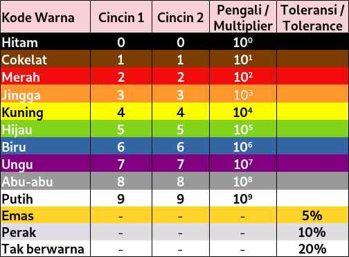
The resistors that we commonly encounter are resistors that have a color code on their body. This resistor has a resistance tolerance of up to 5% for resistors that use 4 color codes, while resistors that use 5 color codes generally have a tolerance of below 1%, where the smaller the resistance tolerance, the more precise the resistor is. Resistor tolerance states that the resistance value of a resistor is considered good if the resistance value is still within the tolerance range, for example: a 1 kΩ resistor has a tolerance of 1%, then the resistor value is considered still good if it has a value of 1 kΩ ± 10 Ω.
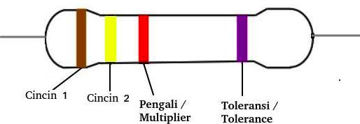
Resistors with 4 color codes
 |
| Figure 5. 4 resistors with 4 color codes |
Image Caption 5:
- The color on ring 1 represents the first number or value
- The color on ring 2 represents the second number or value
- The color of ring 3 indicates the size of the multiplier
- The color of ring 4 represents the resistor tolerance value
Table 2. Four resistor color codes
 |
Figure 6 shows an example of a resistor using 4 color codes
|
|
| Figure 6. 4k7 resistor tolerance ±5% |
Resistors with 5 color codes
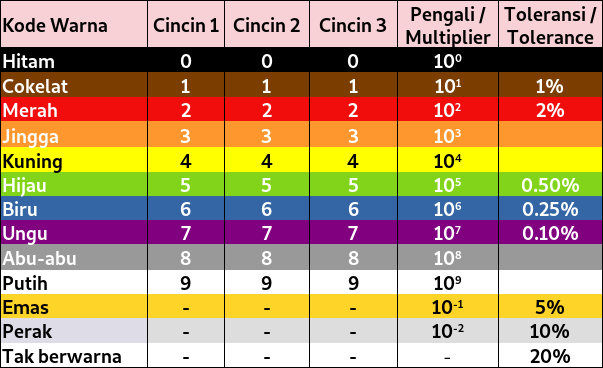
Resistors with 5 color codes generally have a smaller resistance tolerance than resistors with 4 color codes so that these resistors have more precise resistance.
 |
| Figure 7. 5 color coded resistor buttons |
Caption Figure 7:
- Ring color 1: Represents the first number or value
- Ring color 2: Represents the second number or value
- Ring color 3: Represents the third number or value
- Ring color 4: States the size of the multiplier
- Ring color 5: States the resistance tolerance of the resistor
Table 3. Resistor Button 5 color codes

Figure 10 shows a resistor with 5 color codes with a resistance value of 4k7 and a tolerance of ± 1%.
 |
| Figure 8. Resistor 4k7±1% |
Variable Resistors
A variable resistor is a resistor whose resistance value can be changed or altered within a certain range of values. Some jeans variable resistor are as follows:
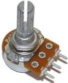
1.Potentiometer
 |
| Figure 9. Potentiometer |
A potentiometer is a variable resistor whose resistance value can be changed by rotating the potentiometer shaft. The use of this potentiometer is very wide, one of which is used for volume on analog radios, as a regulator tone control on. on amplifier, Variables in the circuit dimmer etc.
2. Trimpot
 |
| Figure 10. Trimpot |
Trimpot is one type variable resistorWhat differentiates a trimpot from a potentiometer is that the trimpot requires a tool to change the resistance value, generally using a tool such as a screwdriver with a minus head.
The total resistance of the resistors is arranged in series
The total resistance of resistors if they are installed in series in a circuit, the total resistance is the sum of the resistances of each resistor. Figure 11 shows resistors arranged in series.
 |
| Figure 11. Resistors arranged in series |
The total resistance of the resistor is 11d:
R total =R 5 +R 6 +R 7 +R 8
Rtotal = 1k + 1k + 1k + 1k
Rtotal = 4kΩ
The amount of electric current flowing in the circuit in Figure 11 is:
I = V/Rtotal
I = 5V / 4kΩ
I = 1.25 mA
The total resistance of the resistors is arranged in parallel
The total resistance of resistors when installed in parallel is the sum of the resistance values of each resistor. Figure 12 shows resistors arranged in parallel.
 |
| Figure 12. Resistors arranged in parallel |
The total resistance of the resistor Figure 12 days per day can be used:
1/R total = 1/R 1 +1/R 2 +1/R 3 +1/R 4
1/R total = 1/1k + 1/1k + 1/1k + 1/1k
1/R total = 1/1k + 1/1k + 1/1k + 1/1k
1/Rtotal = 4/1k
Rtotal = 1k/4 = 0.25kΩ
The amount of current flowing in the circuit in Figure 12 can be calculated as follows:
I = V/Rtotal
I = 5V / 0.25kΩ
I = 25mA
반응형
'Eelektronika' 카테고리의 다른 글
| JFET (Junction Field Effect Transistor) (0) | 2024.04.26 |
|---|---|
| JFET (Junction Field Effect Transistor) (0) | 2024.04.26 |
| N-MOSFET Amplifier Common Source (0) | 2024.04.26 |
| PWM Arduino Uno (0) | 2024.04.26 |
| Rectifier diode (0) | 2024.04.26 |