MOSFETs can be used Metal Oxide Semiconductor Field Effect Transistors Namely a transistor where the amount of electric current flows through the terminal Drain Source The transistor depends on the amount of voltage at the terminal Gate the transistor. This transistor is a type of FET which is different from the JFET which has electrodes Gate MOSFETs are made from metal oxide (metal oxide) which is electrically isolated from channel No channel Poleh very thin layer material, commonly known as silicon dioxide (SIHI2). Thin insulating layer on Gate can be thought of as a trigger and this insulation creates resistance enter MOSFET pads can use MΩ and batteries to connect them.
MOSFET has 4 terminals viz Source (S), Drain (D), Gate (G)And Body (B). The body is always connected directly to the terminal Source So physically there are only three terminals, namely Gate, SourceAnd Drying. There are many different types of JFETs and MOSFETs that can be connected to N channel MOSFET or often called NMOS and P channel MOSFET or often called PMOS. Set the MOSFET in this new pad mode depletion in fashion improved.
Install and use MOSFET
Figure 1 shows the basic structure of a MOSFET n-channel. MOSFET structure is different from JFET where MOSFET has a thin layer oxide (SiO2) under the metal electrode pad Gate which functions as an insulator so that the MOSFET has impedance Gate very high, theoretically infinite so it can be said at Gate No current flows even though voltage is applied. MOSFET metal pads are generally made from Aluminum (Al). N+ Figure 1 shows doping high on N-type substrates. |
| Figure 1. P type MOSFET |
MOSFETs can be used in different modes depletion in fashion enhancement. Image of P symbol channel The MOSFET is shown in Figure 2.
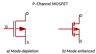 |
Figure 2. Symbol P-Channel MOSFET (PMOS) |
N symbol channel The MOSFET is shown in Figure 3.
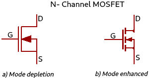 |
| Figure 3. Symbol N-Channel MOSFET (NMOS) |
MOSFET N-Channel Fashion Upgrade
MOSFET works on fashion upgrade Means MOSFET n-channel This may be a different option for the terminal Source-Gate (+VG.S) and on the terminal Drain Source (+VDS). When the MOSFET is energized VG.S = 0 Voltage 4 pieces channel You can use it and use it in your terminal Drying to Source I can't wait to install terminal pad Drying–Source (VDS). He also worked on MOSFETs. 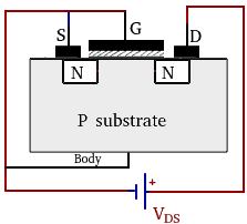 |
| Figure 4. NMOS fashion upgrade VG.S 0 volts |
Figure 5 shows a MOSFET n-channel This newer mode improved where at the moment Source-Gate given voltage +VG.S Then the substrate P minority carriers are attracted to channel surrounding area Gate Or the band area below the surrounding oxide, but cannot cross or pass through the S oxide layerIHI2 because this layer functions as an insulator. On voltage +VG.S Minimum electronic content and storage Gate form channeland this minimal force is called stress threshold (VQ). Moment channel It can also be used to display data on the terminal Drying to Source. Moment +VG.S Raise it higher then channel This may happen to other people Drying (ID) the greater it is.
 |
| Figure 5. NMOS mode. mode improved with +VG.S |
Please don't forget to share it with me channel, thinning layer also formed nearby channel You can also choose from six different locations. Depletion happened because there was prayer PN Junction who gets backwards biased ie PN Junction on. on Drying and substrate, then PN Junction on. on Source and substrate.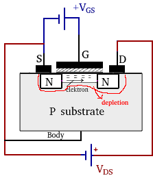 |
| Figure 6. Channel And thinning layer NMOS |
I have an explanation of Figures 4, 5 and 6 of the days that I left out the other side of the story 7.
 |
| Figure 7. NMOS fashion upgrade |
Figure 7 explains that when the voltage +VG.S This book is better than that threshold (VQ) layers then channel There are many types of electronic devices that are connected to electronic devices and installed with batteries channel (Gate) What excites the flowing will get bigger but the area channel on. on Drying it gets narrower if VDS I'm sorry, I'm sorry thinning layer gets wider due to tension come back on. on PN Junction around Drying The bigger the consequences VDS enlarged. By expanding thinning layer in the area Drying means hole Increasingly causes fewer electrons in the area Drying This is the reason why I have no choice but to do it channel around Drying narrowed. Current voltage VDS There are different types of people who want to return to work channel on approx Drying The narrowest is called voltage pinch off (VP) then the current Drying (ID) experiences saturation where the current is constant even though the voltage is constant VDS raised again.Figure 8 shows that the current voltage VDS Less than or equal to the voltage threshold (VQ) I do not know what to do ID Or current on Drying equal to zero. Right side area place VDS It is called this saturation, and this saturation area can be reached at this time VDS >= (VG.S -VQ).
 |
| Figure 8. NMOS characteristic curve fashion upgrade |
|
From Figure 8 days at once to go to another room VG.S = 0 NMOS can be used for NMOS usually dead.
MOSFET N-Channel This is the problem Thinning Mode
MOSFET n-channel Work on thinning mode It's worth it Source-Gate given a negative voltage bias (-VG.S) And Drain Source given a positive voltage bias (+VDS). MOSFET illustration n-channel on. on thinning mode shown in figure 9.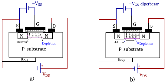 |
| Figure 9. MOSFET N-channel mode removal |
|
Figure 9a shows this moment VG.S I had no choice but to use it (-) with a properly working electric motor, and hole Pulled to the region near the oxide so that the number of free electrons in the N- regionchannelI'm trying to figure out what's going on here Drain Source (IDS) reduce.
If voltage -VG.S I have no choice but to use the electronic devices and devices that I need n-channel The more it causes the smaller the electric current to flow. This one will start the next day 9b.
In general thinning mode This MOSFET has been replaced with a new MOSFET –VG.S To reduce the current flowing at the terminal Drain Source. |
| Figure 10. NMOS characteristic curve Erasure mode |
|
From Figure 10 it can also be seen that mode depletion moment VG.S = 0 NMOS is installed in the terminal Drain Source Given voltage, so NMOS mode depletion also called NMOS usually on.
MOSFET P-channel (PMOS)
MOSFET P channel (PMOS) is used to replace MOSFETs n-channel mode. mode enhancementthe difference is in the terminal Drain Source given voltage (negative-VDS).
Figure 11 shows the basic structure of a MOSFET P channel. MOSFETs have a thin layer oxide (SIHI2) under the metal electrode pad Gate which functions as an insulator so that the MOSFET has impedance Gate very high, theoretically infinite so it can be said to be Gate No current flows even though a bias voltage is applied. MOSFET metal pads are generally made from Aluminum (Al). P+pad Drying And Source show doping high on the P type substrate. The widest area of white is the N type substrate, this substrate is connected to body.
MOSFET Improved P-Channel Mode
PMOS mode enhancement on the terminal Drain Source voltage (negative-VDS) And Source-Gate is also given a negative voltage (-VG.S). Current voltage VG.S This book is better than that threshold (|VG.S| > |VQ|), hole (minority carrier) The substrate pad is not attracted to the surrounding area Gate but can't penetrate Gate because there is an oxide insulator there. By gathering hole around Gate There's no way channel and when VDS No voltage or a voltage of 0 Volts is given then the shape of the P-regionchannel The same size or flat as shown in Figure 12.
On fashion upgrade This is what I did channel there is thinning layer Because PN Junction on. on Source And Drying always experience biased saved.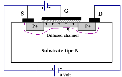 |
| Figure 12. PMOS fashion upgrade with VDS 0 |
|
Moment VG.S < 0 I do not know channel it's getting wider because hole More and more gathered around Gate. If voltage -VDS Make the area bigger channel around Drying This is the first time you can read it again 13. Narrowing this down channel around Drying Caused by negative voltage on Drying interesting hole on approx Drying And causes current to flow from Source to Drying.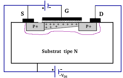 |
| Figure 13. PMOS fashion upgrade with -VDS |
|
Current voltage -VDS Some people have difficulty doing this channel around Source It becomes narrower until it reaches a tension condition pinch off (Vpinch off) where is the current Drying ID Saturation and Constant withstand voltage -VDS I am sorry. The saturation area occurs when |VDS| >= |VG.S| – |VQ|
MOSFET P-Channel Mode Elimination
Fashion depletion PMOS device installed Drain Source voltage (negative-VDS) And Source-Gate good criticism (+VG.S).
At this time VG.S equals 0 and Drain Source given voltage -VDS so hole There is a large menu at the media end and a time board with electronic boards on different media and menus. P channel. If voltage +VG.S There are other options hole in the area P channel This is what makes people happy ID on. on Drying also decreased. |
| Figure 14. PMOS Curve Characteristics thinning mode |
|
For PMOS depletion Everything is in the right place.
Note: Voltage Threshold (VQ) on other pages is referred to as VGS threshold


