itutorial - Arduino Uno can be used to read analog voltages (has an ADC) on pins or terminals A0 to A5 which are commonly referred to as analog pins which are capable of reading 6 different analog voltages. There are many members who have had the same experience with the control panel. output analog voltage from 6 different sensors.
 |
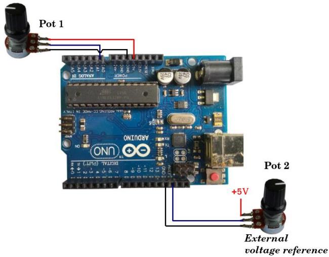
| Figure 1. Analog pins and external reference voltage pins |
This can help you find the information you need to use the dc analog to use it to use the Arduino Uno ADC. Ac analog voltage will be discussed another time on a different page because it requires mathematical understanding.
However, what you need to know is that the readings on the analog pins are done alternately, in other words the analog voltage readings cannot be done simultaneously, for example if you use 3 temperature sensors to measure different room temperatures where the pins are A0, A1 and A2 maybe is also the same size as the A0 pad, which can also be used as an A1, or A2 pad. There is no stipulation in which order the pins should be read first because it depends on you or programmer.
Some things you need to know before creating a project using the Arduino Uno ADC:
1. Arduino Uno has default internal reference voltage 5 Volts.
Now default The Arduino Uno ADC works with an internal 5 Volt reference. If you write a program to read the voltage on the analog pin then the voltage range that can be measured or read is 0 to 5 Volts. If you want Arduino to read analog voltage from output sensors or other devices that have output Maximum 5 Volts, can also be used to install programs with the Arduino Uno analog pin pad.
2. Arduino Uno is equipped with an internal power supply of 1.1 Volts.
If the voltage is analog output Electronic devices or sensors that are read on analog pins have a maximum value of 1.1 Volts, so it is necessary to use an internal reference voltage. To use the Arduino Uno's 1.1 Volt internal voltage reference you need to write a command Analog reference(INTERNAL) on block setup void(){}. An example of writing the use of the Arduino Uno's 1.1 Volt internal voltage is:
void setup(){
analogReference(INTERNAL);
}
3. Arduino Uno is more suitable for external devices.
This is similar to other analog pins. The Arduino Uno has a maximum voltage beyond 1.1 Volts and 5 Volts (under 5 Volts) so the most suitable option is to use an external reference voltage by connecting the AREF pin of the Arduino Uno to the desired external dc voltage (maximum 5 Volts) because with this you can turn on the reference voltage as desired. Embed the REF data in Figure 1. Or if you want the external voltage to be changed because for testing or trial reasons you need a potentiometer connected to the aREF pin as shown in Figure 2 below.
 |
| Figure 2. Illustration of the Arduino Uno using an external reference voltage |
To use an external reference voltage it is necessary to write a command Analog reference(EXTERNAL) on the block void setup(){}. An example of writing how to use the Arduino Uno's external voltage is as follows:
void setup(){
analogReference(EXTERNAL);
}
4. Arduino Uno has an ADC resolution of 10 bits.
The resolution of the Arduino Uno ADC is 10 bits where each analog voltage reading from each similarity taken is translated into a 10 bit binary number or if it is made decimal then the maximum voltage value on the analog pin reaches the reference voltage value so the reading result is 1023.
5. The Arduino Uno ADC conversion time is 13 clock cycle
Arduino Uno ADC analog voltage conversion time to digital under normal conditions single ended is 13 clock cycle. The Arduino Uno ADC has 7 bits prescaler to determine value sample rate The ADC can use a prescaler set to 128 and an Arduino Uno interface. clock source of 16 MHz so that's how big it is sample rate The maximum allowable is 16MHz /128 /13 = 9615 Hz or rounded 9600 Hz.
Project to Make an Arduino Uno ADC
There are new Arduino devices available in the Arduino IDE, and there is also a blog on the list of people working on the IDE to download them later. source code library You can even edit it where the Arduino IDE is not equipped with this feature.
I will also download the Arduino Uno ADC project from the Sloeber IDE. Sloeber provides installer For operating systems on Linux, Windows and MacOS. Use the following link to download the latest IDE:
- Run Sloeber by clicking executable file sloeber-idea.
- Click menu New-File-Arduino Sketch.
 |
| Figure 1. Arduino Sketch Menu |
- Here's what I say about it. Then click the button Next.
 |
| Figure 2. Window New Arduino sketch |
Fill it in Platforms folder, Board And there are still other things to discover on the Arduino Uno. Then click the button Next.
 |
| Figure 3. Window Arduino information |
- This is the most important thing in the world Finish.
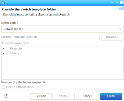
- Figure 4. Window sketch template folder
 |
| Figure 4. Options window sketch templates folder |
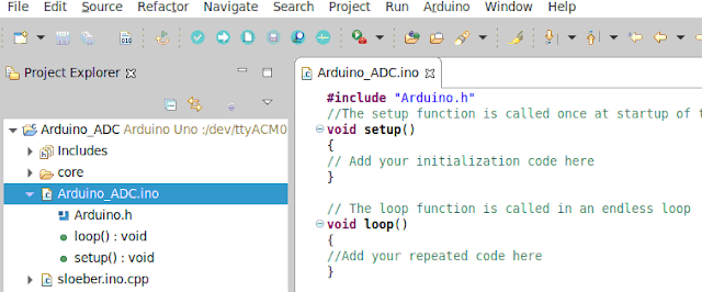
- On tab Project Explorer click Arduino_ADC.ino. How to install Arduino_ADC.ino and install the Arduino IDE program.
- Figure 5. Arduino project
 |
| Figure 5. Arduino project |
Writing the Arduino Uno ADC program and explanation
Figure 6 shows the program for reading the dc analog voltage on pin A0 of the Arduino Uno.
 |
| Figure 6. DC voltage reading program on analog pin A0 |
Use the explanation for writing the Figure 6 day program:
floating value;
Is a global declared variable “value” with data type float Where has a value of two numbers after the comma.
floating results :
Declaring a global variant “result” with data type float.
void setup() { }
This is the block where the program initialization is written. The initialization program is a program that is only executed once when the Arduino board is turned on so that it is not entered repeatedly or circle. Additionally, the menu is empty and the blocks are in the same place, but can also be used with the help of others.
empty loop() {}
It is a block where all the commands or programs written in this block are executed sequentially from the first or top to the bottom or last then it will be repeated from the beginning again and will continue to be repeated.
Serial.start(9600);
Please note that there is no connection to a serial communications port with a baud rate of 9600 bps.
value = analogRead(A0);
Order analogRead(A0) This is a command to read the analog voltage on pin A0 of the Arduino Uno, then convert the voltage that was read into a binary or digital number and then store it in a value variable with a data type. float. When the analogRead(A0) command is executed the Aarduino Uno ADC only takes one similar analog voltage applied to the Analog A0 pin.
Please remember that all processes in Arduino use binary numbers, although when writing programs generally use decimal.
result = ((value / 1023) * 5.0);
Variable mark Saves the reading results of analog pin a0 with data type float where the value depends on the amount of voltage on Analog pin A0 where the maximum value is variable mark is 1023 if the voltage on analog pin A0 reaches 5 Volts.
Divider numbers 1023 This will not do you any good mark No need to install Arduino Uno ADC which is 1023 (10 bit). The multiplier number 5.0 functions to convert the part number 1023 into a voltage and the value 5.0 is used because it uses a reference voltage of 5 Volts.
Serial.print(“A0 : “);
This may be the reason for using the main text “A0:” on the IDE serial monitor for both Arduino IDE and Sloeber IDE.
Serial.print(result);
This is a command to display the results of analog voltage readings on analog pin A0 on the IDE serial monitor. The results displayed are placed next to the right text “A0:”.
Serial.println(“Volts”);
Command to display the words “Volt” on the IDE serial monitor in a position next to the command result Serial.print previously. Order Serial.print This will also help you read the text.
Writing a program to read analog voltage on analog pins A0 and A1
To read two analog voltages, connect an analog voltage source to the Arduino analog pin, for example A0 and A1. The analog voltage source is generally the output of the sensor, in this experiment two potentiometers were used as shown in the circuit in Figure 7.
 |
| Figure 7. Two analog voltages on pins A0 and A1 |
The essence of writing a program to read more than one analog voltage is to take a reading on one analog pin followed by reading another analog pin as shown in Figure 8.
 |
| Figure 8. Analog voltage reading on pins A0 and A1 |
Also, there are better sensors output analog voltage (maximum 6), you can read the analogRead reading program from A0 to A5 alternately or sequentially with the basic example in Figure 8.
Problems with analog voltage reading on multi pins or multi channel
On multi reading channel or multi analog pin problems will occur where the reading is disturbed by the reading value on channel or other analog pins when transferring or switch from 1 analog pin to another analog pin. To carry out the test, you can use the Figure 8 program, you only need to install 1 potentiometer for example on the pin A0 only, to pin A1 You will definitely feel comfortable with this place. While the program is running you will see that it is reading on the pins A1 has a value almost close to the pin reading A0. This also works with potency measuring pads A0 then the pin will be automatically read A1 which is not connected to any component also changes with a value almost the same as the pin reading results A0.
Currently the author is still looking for a way to find out how to solve this problem because if you connect the sensor to a voltage output the order of Volts and milli Volts on the other pins will affect the reading value on the analogue which has the order of milli Volts.
This is what I did renew No need to worry about the problem, the art of writing is connected to this main Problem, and also works with the control device and 2 internal ADCs.
The temporary solution is to read twice on each analog pin that will be read because it will eliminate or replace the value of the other analog pin with the value of the pin being read at that time, thereby minimizing interference with voltage values from other pins.


